
Energy monitor PZEM-004T
PZEM004T-energy monitor with UART.
Allows you to get the parameters of the power grid - one parameter every 0.6 seconds: voltage, current, power, energy consumed,
as well as frequency and power factor.
The module has a galvanic isolation between the measuring circuits and the UART output, which provides
security of the connected reader.
There are two versions of the module 0-10A, without a current transformer, and 0-100A with a transformer.
There are two versions of the module 0-10A, without a current transformer, and 0-100A with a transformer.
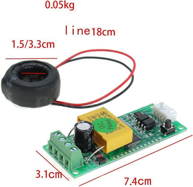
Module features
• Measurement of the current AC voltage 80-260V
• Measuring current 0-100A (0-10A)
• Measurement of active power 0-22kW (0-2, 2 KW)
• Measurement of electricity consumption
• Measurement accuracy 1%
• Operating frequency 45-65Hz
• Serial interface UART with speed 9600
• The supply voltage of 5V
• Measuring current 0-100A (0-10A)
• Measurement of active power 0-22kW (0-2, 2 KW)
• Measurement of electricity consumption
• Measurement accuracy 1%
• Operating frequency 45-65Hz
• Serial interface UART with speed 9600
• The supply voltage of 5V
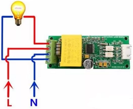
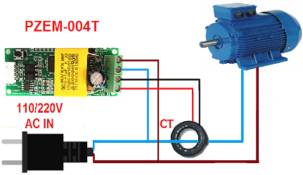
Wiring diagrams of the power part.
0-10A
0-100A
The module uses Modbus RTU Protocol via galvanic
decoupled UART interface. Due to the fact that the interface is galvanically isolated,
an additional source is needed to power it.
You can read the data from the module both with the help of the MC and with the help of a computer,
using a USB <-> UART adapter, and any program that can read Modbus RT.
List of registers PZEM-004T.
| Number | Description |
|---|---|
| Input Registors | |
| 0 | Voltage in volts *10 |
| 1 | Current in milliamps |
| 3 | Power in Watts *10 |
| 5 | Watt-hour counter |
| 7 | Frequency in Hertz*10 |
| 8 | Power factor*100 |
| Holding Registors | |
| 2 | Modbus address of the device. |
With the standard Modbus, it will not be possible to reset the watt-hour counter, as the manufacturer has done for this
non-standard function (46).
Connection diagram of the module to the PC
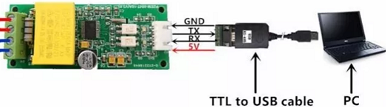
To simplify the reading of the module data and setting the device address, a program was created PZEMSettings
.
This program was made using Ftprog-Scada and the archive contains the source file for the program FLProg (PZEM-004T. flp).
The FLProg program has a block
for this module that allows you to read the data from the module, as well as reset the watt-hour counter if necessary.
Connection diagram of the module to MK
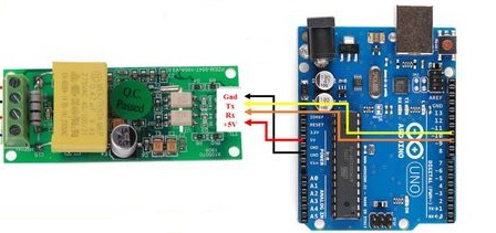
No address setting is required for this connection. The survey is conducted using a broadband request to address 248.
It is also possible to connect several modules to one UART in a common loop using modules UART < - > RS485
Connection diagram
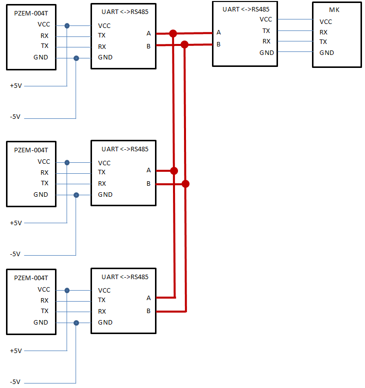
With such a connection scheme, it is necessary to register a unique address in each module, which is then used in the data reading block c PZEM-04T